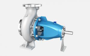
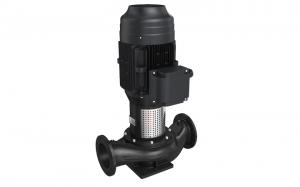
The principle of water transfer pump:
The water transfer pump, including pump body, pump cover, impeller with sealing ring and induction wheel; The pump body and the electric transfer pump cover are equipped with the sealing ring. The shaft of the rotor parts is loaded into mechanical seal, impeller and induction wheel, and use the induction wheel nut to lock, the pump body, the pump cover is bolted, the pump cover and the bearing suspension are fastened by the bolt, the left end of the rotor assembly is mounted on the pump body through the guide bearing. The right end of the rotor component is supported on the bearing suspension and the coupling is connected to the coupling. The coupling is connected to the motor. The induction wheel is composed of two sets of spiral shape space, and the three blades of the circular direction are connected with the front and rear cover plates to make up the impeller. Due to the increase of the surface curvature inducer blade, and it has large suction pumps, and it reduces the water pump necessary NPSH, it improves the anti-cavitation performance of the inline transfer pump, so as to ensure the reliability of
close coupled centrifugal pump used in harsh working environments, and prolongs the service life of the pump, reduces the cost and improves the working efficiency.
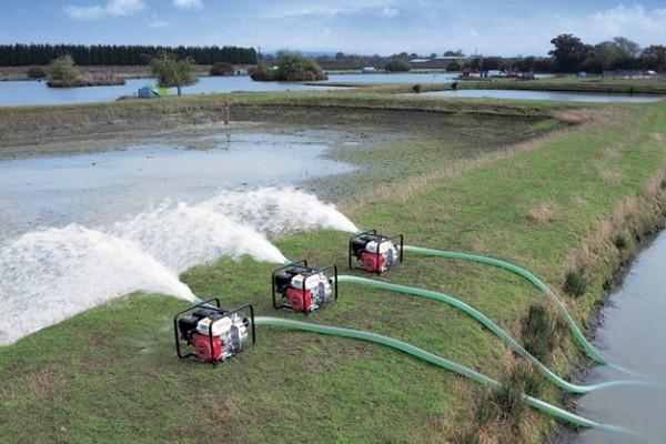
The application of water transfer pump:
Water transfer pump has different uses due to different conveying liquid medium, flow rate, lift range, structural form, and material. To sum up, it roughly can be divided into:
1.urban water supply 2. sewage system 3. civil engineering, construction system 4. agricultural water conservancy system 5.power station system 6. chemical system 7. oil industry system 8. mining metallurgical system 9. light industrial system 10. ship system
Working principles:
1. Volumetric electric water transfer pump: use the working chamber volume periodic variation to transport liquid.
2. Vane pump: use the interaction of the blades and the liquid to transport the liquid.
The features of water transfer utility pump:
-
Excellent performance
-
Strong motor and reasonable body design
-
High efficiency, low noise.
-
The water area adopts special treatment, not only not easy to rust but also good wear resistance.
-
It is economical and practical.
-
Energy conservation design and reasonable prices will help you improve your life quality.
-
Setup/assembly is simple and easy to use
-
Designed with new technology to make assembly and maintain easy. It has a self-priming function.
The flow control method of fresh water transfer pump:
1. Speed control method. Control the running speed of the motor (pump) by means of the frequency converter to achieve the purpose of flow controlling: the faster the speed, the larger the flow.
2. Valve opening control method: by controlling the opening of the outlet valve, the discharge flow of the pump is adjusted.
3. Pump flow: the amount of liquid that is pumped out in the unit time (generally expressed in volume). Volume flow has nothing to do with the nature of the liquid transported(it has nothing to do with the density of the liquid).
4. Volume flow is indicated by Q, the unit is: m³/s(cubic meter per second), m³/h (cubic meter per hour), l/s (liter per second), etc.
The maintenance of hot water transfer pump:
1. Check the pump and motor regularly and replace the damaged parts;
2. When the long-term outage, the flow channel should be cleaned and the power supply should e cut off.
3. No empty operation;
Common failures & causes & solutions of the inline water transfer pumps:
1. Failure: the pump does not absorb water and the pressure gauge is beating violently.
Reason: the infusion of water is not enough. The pump has air in it. The suction pipe and the gauge leak air.
Solution: pour in enough water. Check the pipeline for air leakage.
2. Failure: the vacuum gauge indicates a high vacuum and the pump still does not absorb water.
Reason: the bottom valve has not opened or seriously blocked. The gerat resistance of the suction pipe.
Solution: check the valve's flexibility and remove the plug. Make the suction piping as simple as possible. Lower suction height.
3. Failure: the outlet pressure gauge indicates that there is pressure and the pump has little or no water.
Reason: water pipe resistance is large. The turn is wrong. Impeller blockage. Not enough speed.
Solution: reduce tube resistance. Check the motor steering. Remove the impeller block. Increase the speed.
4. Failure: flow rate is lower than the designed flow.
Cause: the impeller of self-priming pump is blocked. Excessive wear of seal ring clearance. Not enough speed.
Solution: remove the plug. Replace the seal ring. Increase the speed to the specified value on the nameplate.
5. Failure: pump vibration
Reason: decentration of the pump shaft and the motor shaft. Impeller imbalance. Excessive clearance between bearings.
Solution: adjust the pump and motor to align the axis. The impeller passes the balance test, the unbalance weight requirement is about 3 grams. Replace the bearing.